Upload Program in ESP12E / ESP12F using Node MCU
How To Program ESP12E / ESP12F using
NodeMCU or ESP8266 in a Very Easy Way
# Components Needed
1. Node MCU or ESP8266
2. ESP12E or ESP12F
3. Few jumper Cables
4. 10k Resistor 2 pcs
# Circuit Diagram & Process
Step - 1
💬 In ESP12E / ESP12F chip, Connect 10K resistor between EN/CH_PD and VCC
💬 In ESP12E / ESP12F chip, Connect 10K resistor between GPIO15 and GND
Step - 2
💬 To bypass the Node MCU chip Connect EN / CH_PD with GND in Node MCU
Step - 3
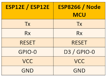
💬 Connect the rest of the pins as per the Table ---
Step - 4
💬 To Add the ESP8266 Library Enter this link into Arduino IDEinto the File > Preferences > Additional Boards Manager URLs field of the Arduino IDE. You can add multiple URLs, separating them with commas.
# After Selecting the Board Write the code and upload it as usual
# After uploading the Program We can Remove all the cables except VCC, GND, RESET, and the Resistors.
# For Power we have to give 3.3v maximum either it will be damaged.
Here is some information about the Pins & syntax of the ESP12E / ESP12F chip
# In ESP12E / ESP12F chip there are
----- 9 Digital Pins [ D0-D8 ]
----- 1 Analog Pin
----- Default digital Pin is 2 [GPIO-2]
----- Syntax is (GPIO pin, OUTPUT)
##################################
When you use only ESP 12E or ESP 12F chip in your Project You have to connect a 10k resistor between RST and VCC, it prevents continue resetting.
##################################
Example ----
digitalWrite(2, HIGH);
// Here GPIO-2 is used which is D4


Comments
Post a Comment